Problem 5-6
Determine the values and draw the diagrams for shear force, bending moment and axial force due to the imposed load on the frame shown in figure 5-6(a). Support at A is hinged and F is roller. Joints at C and E are rigid joints.

Figure 5-6(a)
Solution:
The support A is hinged, it will have two reactions (horizontal HA and vertical VA). Support F is roller, it will have only vertical reaction VF. To calculate the support reactions we apply equilibrium equations.
Assuming horizontal reaction (HA) at A in the left hand direction and apply equilibrium of the frame in horizontal direction, we get;
Σ H = 0; ---- (Eq. 1)
- HA + 5 = 0 ;
Therefore reaction HA = 5 kN in the left hand direction.
Consider equilibrium of frame in vertical direction, we get;
Σ V = 0;
VA + VF - 10 x 2 = 0;
VA + VF - 20 = 0; ---- (Eq. 2)
Consider rotational equilibrium of frame and taking moment of all the forces about point A, we get;
Σ MA = 0;
VF x 5 - 10 x 2 x 1 - 5 x 3 = 0; (considering clockwise moment as negative and anti-clockwise moment as positive)
5 VF - 20 - 15 = 0; ---- (Eq. 3)
We get, VF = 7 kN
Now we substitute this value of VF in Eq. 2 to get the value of VA;
VA + 7 - 20 = 0; therefore VA = 13 kN. Negative sign indicates that the reaction at A will be in the downward direction as shown in the free body diagram of the frame.
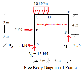
Figure 5-6(b)
Now we draw the free body diagram of each member ABC, CDE and EF as well as the free body diagram of rigid joints C and E and apply the equilibrium equations.

Figure 5-6(c)
We cut a section just before rigid joint C. This will give three unknowns at the section VC, HC, and MC.
Consider horizontal direction as x-axis and vertical as y-axis.
Apply equilibrium in horizontal direction.
Σ Fx = 0; - 5 + 5 - HC = 0. This gives HC = 0.
Apply equilibrium in vertical direction.
Σ Fy = 0; 13 - VC = 0. This gives VC = 13 kN
Apply moment equilibrium by taking moment of all the forces at A. Considering clockwise moment as negative and anticlockwise as positive, we get;
Σ MA = 0.
- 5 x 6 + 5 x 3 + MC = 0.
This yields MC = 15 kNm as shown in figure.
Now consider the equilibrium of rigid joint C. These calculated values of HC, VC and MC will be now applied in equal and opposite direction at C. There is no horizontal force at C. The rigid joint C will transfer these values of VC and MC to the other member CDE as shown in figure 5-6(c).
There is no horizontal force acting on CDE. We consider wquilibrium in horizontal direction.
We apply Σ Fy = 0; 13 - 10 x 2 + VE = 0.
This gives VE = 7 kN.
Apply Σ MC = 0. We get - 15 - 13 x 5 + 10 x 2 x 4 + ME = 0. Therefore ME = 0.
Now apply equal and opposite value of VE on the other side of the section at E on the rigid joint E and transfer this force to member EF on the other side of the joint.
We consider the quilibrium of vertical member EF and confirm that Σ FY = 0; This shows that our calculations are correct. The updated Fee body diagram is shown in Figure 5-6(d)
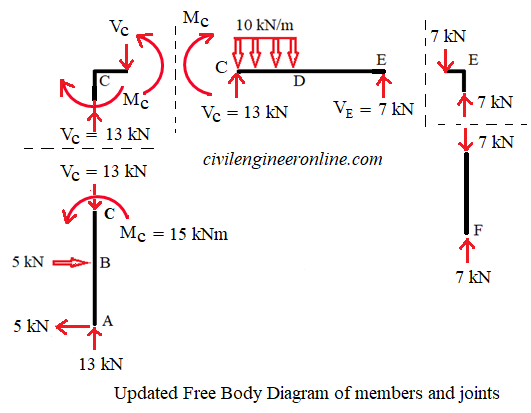
Figure 5-6(d)
Now we will draw Shear Force Diagram (SFD), Bending Moment Diagram (BMD) and Axial Force Diagram (AFD) of each member separately. We advise you to see our solved example Problem 5-2 for more knowledge about SFD and BMD of beam.
Shear force diagram, Bending Moment diagram and Axial Force diagram:
For member AB, we will consider the origin at A. All the forces acting perpendicular to the member will cotribute to shear force and bending moments while the forces along the length of the member will contribute to axial force. Compressive axial force is taken as negative and tensile is taken as positive.
SFD, BMD and AFD for member ABC are shown in Figure 5-6(e)
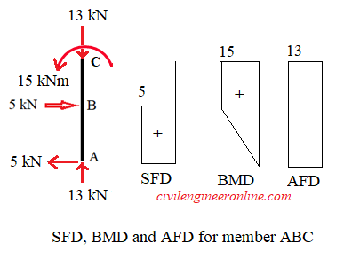
Figure 5-6(e)
For member CDE, we will consider the origin at C. We notice that there is no axial force in the member CDE. SFD and BMD is drawn by using the sign conventions as explained in Problem 5-2
SFD for CDE shows that there is a point of zero S.F. between C and D this means maximum bending moment will occur at this point. We can calculate this point by considering similarity of triangles in the SFD as follows;
13/5 = x / (2 - x); which gives x = 1.44 m. Therefore maximum B.M. will be at a distance of 1.44 m from C and equal to
Mmax = 15 + 13 x 1.44 - 10 x 1.442/2 = 23.352 kNm
BMD will be parabolic under the uniform load. The SFD and BMD for CDE are shown in Figure 5-6(f)
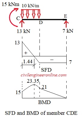
Figure 5-6(f)
For member EF, we consider the origin at E. The free body diagram of EF shows that member EF is subjected to only the axial force therefore there will be no shear force and bending moment in EF. The axial force diagram (AFD) for EF is shown in Figure 5-6(g)
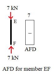
Figure 5-6(g)
You can also use following calculators for Bending moment and shear force
Bending moment calculator for CantileverBending Moment calculator for Simply supported beam
Excellent Calculators
Stress Transformation Calculator
Calculate Principal Stress, Maximum shear stress and the their planes
Calculator for Moving Load Analysis
To determine Absolute Max. B.M. due to moving loads.
Bending Moment Calculator
Calculate bending moment & shear force for simply supported beam
Moment of Inertia Calculator
Calculate moment of inertia of plane sections e.g. channel, angle, tee etc.
Reinforced Concrete Calculator
Calculate the strength of Reinforced concrete beam
Moment Distribution Calculator
Solving indeterminate beams
Deflection & Slope Calculator
Calculate deflection and slope of simply supported beam for many load cases
Fixed Beam Calculator
Calculation tool for beanding moment and shear force for Fixed Beam for many load cases
BM & SF Calculator for Cantilever
Calculate SF & BM for Cantilever
Deflection & Slope Calculator for Cantilever
For many load cases of Cantilever
Overhanging beam calculator
For SF & BM of many load cases of overhanging beam
More Links
Civil Engineering Quiz
Test your knowledge on different topics of Civil Engineering
Research Papers
Research Papers, Thesis and Dissertation
List of skyscrapers of the world
Containing Tall building worldwide
Forthcoming conferences
Containing List of civil engineering conferences, seminar and workshops
Profile of Civil Engineers
Get to know about distinguished Civil Engineers
Professional Societies
Worldwide Civil Engineers Professional Societies
Keep visiting for getting updated or Join our mailing list
Search our website for more...
PleaseTell your Friends about us if you find our website useful
Other Useful Links