Problem 5-2
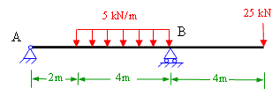
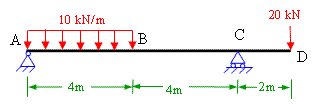
Determine the values and draw the diagrams for shear force and bending moment due to the imposed load on simple supported beam shown in figure 5-2(a)
Figure 5-2(a)
Solution:
The simple supported beam is a beam which has one end hinged and the other roller supported. Hinged support will have two reactions (vertical and horizontal) and roller will have one (vertical). In the case of beam shown in figure 5-2(a), there is no horizontal force and hence the hinge support will have only one reaction. The given beam has two unknown reaction components which are calculated in Prob 4-1 as Ay = 66 kN and By = 24 kN;
Shearing force values:
Shear force at a section is the algebraic sum of the all the forces on either side of the section. Here we consider the forces on the left hand side of the section and take upward force as positive and downward force as negative. Wherever there is a point load we have to calculate the values of shearing force on both the sides (left and right) of that section as there will be a sudden change in the shear force values at that point.
FA(left) = 0
FA(right) = 66 kN;
FC = 66 - 20 x 4 = -14 kN;
FD(left) = 66 - 20 x 4 = -14 kN;
FD(right) = 66 - 20 x 4 - 10 = -24 kN;
FB(left) = -24 kN;
FB(right) = 0;
To draw the shear force diagram we take the distances on x-axis and the shear force values on y-axis and join the points. Wherever there is point load the shear force diagram will be parallel to x-axis and in case of uniform load the shear force diagram is a sloping straight line as shown in shear force diagram (SFD) plotted in figure 5-2(b)
Bending moment values: The bending moment at a section is the algebraic sum of the moment of all the forces on either side of the section. Hogging bending moment is taken as negative and sagging bending moment as positive. Click here to get more about nature of bending moment diagram due to different loadings.
MA = 0;
MC = 66 x 4 - 20 x 4 x 2 = 264-160 = 104 kNm;
MD = 66 x 8 - 20 x 4 x 6 = 528 - 480 = 48 kNm;
MB = 0;
To draw the bending moment diagram the distances are taken on x-axis and bending moment values on y-axis. Bending moment diagram will be a straight line when there is point load and it is parabolic when there is uniformly distributed load (udl). The values of bending moment are plotted in BMD in figure 5-2(b)
Figure 5-2(b)
Throughout the span the bending moment is sagging in nature. To determine the maximum bending moment for the beam we use the relationship between shearing force and bending moment which says that the rate of change of bending moment (dM/dx) is equal to the shearing force (Fx) at the section. For maximum value of any function its first derivative should be equal to zero. Therefore at the point of maximum bending moment the shearing force must be equal to zero. From the shear force diagram it is clear that the shear force is zero between A and C. The point of zero shearing force can be easily determined by using the property of similar triangles.
Hence, 66/x = 14/(4-x) ;
Which yields, x = 3.3m;
Now calculate the bending moment at x = 3.3m which will be the maximum bending moment for this beam. Therefore,
Mmax = 66 x 3.3 -20 x (3.3) x (3.3/2) = 108.9 kNm;
You can visit the following links of solved examples on Bending moment and shear force calculations and plotting of diagrams
You can also use following calculators for Bending moment and shear force
Bending moment calculator for CantileverBending Moment calculator for Simply supported beam
Excellent Calculators
Stress Transformation Calculator
Calculate Principal Stress, Maximum shear stress and the their planes
Calculator for Moving Load Analysis
To determine Absolute Max. B.M. due to moving loads.
Bending Moment Calculator
Calculate bending moment & shear force for simply supported beam
Moment of Inertia Calculator
Calculate moment of inertia of plane sections e.g. channel, angle, tee etc.
Reinforced Concrete Calculator
Calculate the strength of Reinforced concrete beam
Moment Distribution Calculator
Solving indeterminate beams
Deflection & Slope Calculator
Calculate deflection and slope of simply supported beam for many load cases
Fixed Beam Calculator
Calculation tool for beanding moment and shear force for Fixed Beam for many load cases
BM & SF Calculator for Cantilever
Calculate SF & BM for Cantilever
Deflection & Slope Calculator for Cantilever
For many load cases of Cantilever
Overhanging beam calculator
For SF & BM of many load cases of overhanging beam
More Links
Civil Engineering Quiz
Test your knowledge on different topics of Civil Engineering
Research Papers
Research Papers, Thesis and Dissertation
List of skyscrapers of the world
Contining Tall building worldwide
Forthcoming conferences
Contining List of civil engineering conferences, seminar and workshops
Profile of Civil Engineers
Get to know about distinguished Civil Engineers
Professional Societies
Worldwide Civil Engineers Professional Societies
Keep visiting for getting updated or Join our mailing list
Search our website for more...
PleaseTell your Friends about us if you find our website useful
Other Useful Links