Problem 3-1
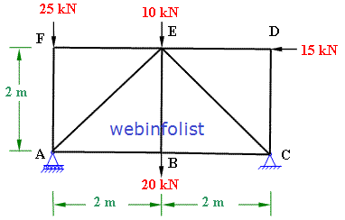
Use method of joints to determine the forces in all the members of pin-jointed plane truss shown in figure 3-1(a).
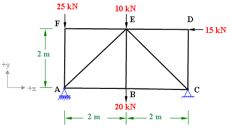
Figure 3-1(a)
Solution:
In the given truss the support at A is roller and C is hinged. First we will find whether this truss is determinate or indeterminate.
Condition of determinacy of plane truss: m = 2j - 3
In this truss j = 6, which requires 2×6 - 3 members for the truss to be determinate. It is confirmed from the figure that there are 9 members in this truss.
Therefore the the given truss is statically determinate.
Reactions at the support:
Support A is on the roller, therefore it will have only vertical reaction and no horizontal reaction. Support C being hinged will experience both horizontal and vertical reactions. (refer to figure 3-1(b).
Considering horizontal reaction at C to be in the +ve x direction and. Applying the conditions of static equilibrium, we get;
(i) Σ Fx = 0; therefore Cx - 15 = 0; eq (1)
Solving the equation we get Cx =15 kN. The positive sign of this value indicates that our assumption in the direction of Cx was correct.
(ii) Σ Fy = 0; yields Ay+ Cy - 25 -10 - 20 = 0;
Ay+ Cy = 55; eq. (2)
(iii) Σ Mz = 0; Considering z-axis perpendicular to the plane and passing through joint A. Take moment of all the forces about z-axis (taking clock-wise negative and anticlock-wise positive);
Ay x 0 + Cy x 4 - Cx x 0 - 20 x 2 + 15 x 2 - 10 x 2 + 25 x 0 =0;
we get Cy = 7.5 kN;
Therefore Ay = 47.5 kN;
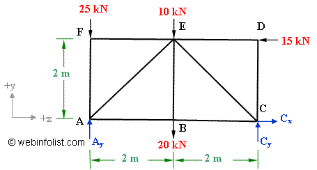
Figure 3-1(b)
Calculation of member forces
We use method of joints to find all the forces in the members of the given truss.
First of all look for the joint which does not have more than 2 unknown forces. In this truss we find that joint D and F have only two unknown forces.
Let's start with joint D; In the beginning assume all the unknown forces as tensile. Tensile forces are shown with an outward arrow whereas compressive forces are shown with an inward arrow at the joint. The forces acting in the +ve directions of axes are taken as +ve whereas those acting in the -ve directions of axes are taken as -ve.
Equilibrium of joint D

Σ Fx = 0;
- FDE - 15 kN = 0;
FDE = - 15 kN The -ve sign of FDE indicates that the assumed direction (tensile) was wrong, therefore the actual nature of force FDE will be compressive.
Σ Fy = 0; => - FDC = 0; therefore FDC = 0
Equilibrium of joint F

Σ Fx = 0; => FFE = 0
Σ Fy = 0; => - 25 - FFA = 0;
FFA = - 25 kN
The -ve sign of FFA indicates that the assumed direction of (tension) for this forces is not correct, therefore the actual direction of force in member FA is to be compressive.
Now the joints A and C have only two unknown forces whereas joint B and E have three unknown forces. So we come to joint A.
Equilibrium of joint A

The force in member AE is making an angle of 45 degree with +x-axis, therefore it has to be resolved into its rectangular components along x-axis (FAEcos45) and along y-axis ( FAE sin45).
Σ Fx = 0; => FAE cos45 + FAB = 0 (i)
Σ Fy = 0; => FAE sin45 + Ay - FAF = 0 (ii)
substituting the magnitudes of Ay and FAF (equal to FFA) into eq.(i) we get
FAE sin45 + 47.5 - 25 = 0;
Therefore FAE = - 22.5/sin45= - 31.82 kN; negative sign of FAE indicates that this force should be in the opposite sense, hence it should be a compressive force of 31.82 kN.
Substituting this value of FAE in eq. (i) yields.
FAB = 22.5 kN;
Equilibrium of joint C
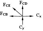
Σ Fy = 0;
FCE sin45 + Cy + FCD = 0 (iii)
FCE sin45 + 7.5 + 0 = 0; Therefore FCE = - 7.5/sin45 = - 10.61 kN; again the negative sign of this force indicates that it should be in the reverse direction, hence compressive 10.61 kN.
Σ Fx = 0; => - FCE cos45 - FCB + Cx = 0 (iv)
Substituting the value of FCE and Cx in eq. (iv) we get;
FCB = + 7.5 + 15 = + 22.5 kN
Equilibrium of joint B
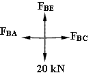
Σ Fy = 0; => FBE = 20 kN
From the previous calculations about joint A and joint C, it is also evident that Σ Fx = 0; because FBA = - FAB and FBC = - FCB ; This confirms our calculations.
| Result of Member forces calculations | ||
| Member | Force (kN) | Nature of force |
| AB | 22.5 | Tensile |
| AF | 25 | Compressive |
| AE | 31.82 | Compressive |
| BC | 22.5 | Tensile |
| BE | 20 | Tensile |
| CD | 0 | |
| CE | 10.61 | Compressive |
| DE | 15 | Compressive |
| EF | 0 | |
You can visit the following links of solved examples
Other Solved examples
More Solved Examples
regularly updated
Excellent Calculators
Stress Transformation Calculator
Calculate Principal Stress, Maximum shear stress and the their planes
Calculator for Moving Load Analysis
To determine Absolute Max. B.M. due to moving loads.
Bending Moment Calculator
Calculate bending moment & shear force for simply supported beam
Moment of Inertia Calculator
Calculate moment of inertia of plane sections e.g. channel, angle, tee etc.
Reinforced Concrete Calculator
Calculate the strength of Reinforced concrete beam
Moment Distribution Calculator
Solving indeterminate beams
Deflection & Slope Calculator
Calculate deflection and slope of simply supported beam for many load cases
Fixed Beam Calculator
Calculation tool for beanding moment and shear force for Fixed Beam for many load cases
BM & SF Calculator for Cantilever
Calculate SF & BM for Cantilever
Deflection & Slope Calculator for Cantilever
For many load cases of Cantilever
Overhanging beam calculator
For SF & BM of many load cases of overhanging beam
More Links
Civil Engineering Quiz
Test your knowledge on different topics of Civil Engineering
Research Papers
Research Papers, Thesis and Dissertation
List of skyscrapers of the world
Contining Tall building worldwide
Forthcoming conferences
Contining List of civil engineering conferences, seminar and workshops
Profile of Civil Engineers
Get to know about distinguished Civil Engineers
Professional Societies
Worldwide Civil Engineers Professional Societies
Keep visiting for getting updated or Join our mailing list
Search our website for more...
PleaseTell your Friends about us if you find our website useful
Other Useful Links
