Problem 5-5
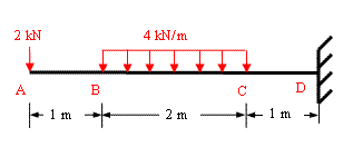
Determine the values and draw the diagrams for shear force and bending moment due to the imposed load on overhanging beam shown in figure 5-5(a) and find the position of point of contra-flexure, if any.
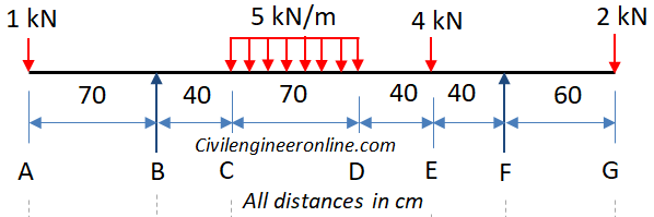
Figure 5-5(a)
Solution:
The given beam has two supports B and F and there are overhanging portions BA and FG on the left and right side respectively. For all the calculations we consider the origin of axes at point A and x-axis is considered positive in the right hand direction whereas y-axis is positive upwards.
This beam is statically determinate as there are only two vertical reactions at the supports, one each at B and F and two equations of equilibrium (∑Fy = 0, ∑M = 0) are available to solve for these reactions.
Now we apply the equations of equilibrium. Let the vertical reactions be VB at B and VF at F.
Algebraic sum of all the forces equal to zero; ∑Fy = 0.
VB + VF – 1 – 5x0.7 – 4 – 2 = 0;
So, VB + VF = 10.5 kN; ………Eqn 1
Algebraic sum of the moments of all the forces about B = 0; ∑M = 0 about point B. For the moments of force we consider clockwise moments as negative and anti-clockwise moments as positive.
1 x0.7 - 5x0.7x(0.4+0.35) – 4 x(0.4+0.7+0.4) + VF x (0.4+0.7+0.4+0.4) – 2x (0.4+0.7+0.4+0.4+0.6)=0;
On simplification we get; VF x 1.9 = - 0.7 + 5x0.7x0.75 + 4x1.5 + 2x2.5;
1.9 VF = 12.925; ……. Eqn 2
Therefore VF = 12.925/1.9;
We get VF = 6.8 kN
Substituting the value of VF in Eqn 1 we get;
VB = 10.5 – 6.8 = 3.7 kN;
Shear Force Calculations
Sign Convention for Shear Force (SF):
- If a force is trying to lift up the left hand side of a section the SF due to that force is taken as positive whereas a force trying to push the left hand side down is taken as negative.
- In case a force lifts the right hand side of a section upward it will be taken as negative and if it is pushing it down the SF will be taken as positive.
In calculating SF we will move along the beam span from left to right (starting from origin at A)
The point A has a concentrated force of 1 kN acting downwards. In such cases we should calculate SF before and after the point. At a section just before A the SF will be zero because there is no force before point A. When we consider a section just after A the shear force will be -1 kN because there is a force of 1 kN at A trying to push the left hand side of the section downwards. We will follow the same procedure to calculate the shear force at all the main points of the beam (A, B, C, D, E, F, G). We get the following values.
SF Just before A = 0
SF just after A = -1 kN
SF just before B = - 1 kN (Note that VB is not considered as it is acting exactly at A, not before A.
SF just after B = -1 + VB = -1+ 3.7 = 2.7 kN (Note that VB is taken positive as it is acting upward)
SF just before C = -1 + VB = -1+3.7 = 2.7 kN (Note that there is no additional load between B and C hence SF at C is same as SF at B)
SF just after C = SF just before C = 2.7 kN (Note that in case of uniform load the SF will be same just before and after the section).
SF at D = -1 + VB – 5x0.7 = -1+3.7 – 3.5 = - 0.8 kN
SF just before E = SF at D = - 0.8 kN
SF just after E = -1 + VB – 5x0.7 – 4 = - 4.8 kN
SF just before F = -1 + VB – 5x0.7 – 4 = - 4.8 kN (Note that there is no additional force between E and F)
SF just after F = -1 + VB – 5x70 – 4 + 6.8 = 2 kN
SF just before G = SF just after F = 2 kN
SF just after G = SF just before G – 2 kN = 0 (2 kN load is acting exactly at G, therefore it will be considered when we calculate SF at a point after G. The shear force diagram (SFD) is shown in Fig 5.5(b)
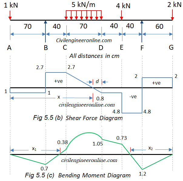
Figure 5-5(b) and (c)
Bending Moment Calculations
Sign convention for Bending Moment (BM):
- The moments which try to bend the beam in such a way that it is concave downwards are known as sagging moments and are taken as positive.
- The moments which try to bend the beam in such a way that it is convex upwards are known as hogging moments and are taken as negative.
As per the definition, bending moment at a section is the moment of resistance of the section. Numerically it is equal to the algebraic sum of moment of all the forces on either side of the section. In this example we will consider forces on the left hand side of the section and take the moment of those forces about the section.
BM at A = 1 x 0 = 0
BM at B = - 1 kN x 0.7 m = - 0.7 kNm
BM at C = -1 x 1.1 + 3.7 x 0.4 = 0.38
BM at D = -1 x 1.8 + 3.7 x 1.1 – 5 x 0.7 x 0.35 = 1.05 kNm
BM at E = -1 x 2.2 + 3.7 x 1.5 – 5 x 0.7 x (0.35+0.4) =0.73 kNm
BM at F = -1 x 2.6 + 3.7 x 1.9 – 5 x 0.7 x (0.35+0.4+0.4) – 4 x 0.4 = -1.2 kNm
BM at G = -1 x 3.2 + 3.7 x 2.5 – 5 x 0.7 x (0.35+0.4+0.4+0.6) – 4 x 1.0 + 6.8 x 0.6 = 0
The bending moment diagram is shown in Fig. 5.5 (c) above.
Maximum Bending Moment will occur at the point where SF is zero.
From SFD it is clear that the SF will be zero somewhere between C and D.
We can determine the point of zero SF by two ways
- Writing the equation of SF at a section between C and D;
Let the section be at a distance x from A
SFx = -1 +3.7 - 5 (x – 1.1)
For this SF at x to be zero we get;
-1 +3.7 -5 (x – 1.1) = 0;
Hence we get x = 2.7/5 +1.1 = 0.54+1.1 = 1.64
- By using the properties of similar triangles;
Let the point of zero SF be at a distance d from point D.
Now equating the ratio of the corresponding sides of the two triangles in the SFD between C and D we get;
0.8/2.7 = d/(0.7- d);
d = 0.16 m
Hence the point of zero SF from A = 1.8 – 0.16 = 1.64 which is same as calculated in (a) above.
Therefore Maximum Bending Moment will be equal to the value of bending moment at a distance 1.64 m from A.
Mmax = -1x1.64 + 3.7(1.64 – 0.7) – 5(1.64 – 1.1)(1.64 – 1.1)/2 = 3.44 kNm
Points of Contra-flexure
From the BMD we can see that there are two points at which the value of BM is zero and have opposite nature of bending on the two sides of these points; such points are known as points of contra-flexure.
One such point is between B and C and the other between E and F.
We can locate these points in an easy way by writing the equation of bending moment for that part of the beam and putting that value equal to zero.
- Point of contra-flexure between B C
Let the first point of contra-flexure be at a distance x1 from A.
Bending moment at a distance x1 from A
Mx1 = - 1 (x1) + 3.7 (x1 – 0.7)
At the point of contra-flexure BM=0;
Therefore we get;
-x1 +3.7 x1 – 2.59=0;
Which yields x1 = 2.59/2.7 =0.96 m
- Point of contra-flexure between E F
Let the second pint of contra-flexure be at a distance x2 from G.
Bending moment at a distance x2 from G
Mx2 = - 2 (x2) + 6.8(x2 – 0.6)
At the point of contra-flexure BM=0;
Therefore we get;
-2 x2 + 6.8 x2 – 4.08 = 0
Which yields x2 = 4.08/4.8 = 0.85 m
You can visit the following links of solved examples on Bending moment and shear force calculations and plotting of diagrams
You can also use following calculators for Bending moment and shear force
Bending moment calculator for CantileverBending Moment calculator for Simply supported beam
Excellent Calculators
Stress Transformation Calculator
Calculate Principal Stress, Maximum shear stress and the their planes
Calculator for Moving Load Analysis
To determine Absolute Max. B.M. due to moving loads.
Bending Moment Calculator
Calculate bending moment & shear force for simply supported beam
Moment of Inertia Calculator
Calculate moment of inertia of plane sections e.g. channel, angle, tee etc.
Reinforced Concrete Calculator
Calculate the strength of Reinforced concrete beam
Moment Distribution Calculator
Solving indeterminate beams
Deflection & Slope Calculator
Calculate deflection and slope of simply supported beam for many load cases
Fixed Beam Calculator
Calculation tool for beanding moment and shear force for Fixed Beam for many load cases
BM & SF Calculator for Cantilever
Calculate SF & BM for Cantilever
Deflection & Slope Calculator for Cantilever
For many load cases of Cantilever
Overhanging beam calculator
For SF & BM of many load cases of overhanging beam
More Links
Civil Engineering Quiz
Test your knowledge on different topics of Civil Engineering
Research Papers
Research Papers, Thesis and Dissertation
List of skyscrapers of the world
Containing Tall building worldwide
Forthcoming conferences
Containing List of civil engineering conferences, seminar and workshops
Profile of Civil Engineers
Get to know about distinguished Civil Engineers
Professional Societies
Worldwide Civil Engineers Professional Societies
Keep visiting for getting updated or Join our mailing list
Search our website for more...
PleaseTell your Friends about us if you find our website useful
Other Useful Links