Problem 7-9
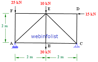
Determine the horizontal displacement of joint C of the pin-jointed truss shown in the figure with the help of method of virtual work. Support B is hinged and C is a roller. For each member, E is 200 GPa , area of cross-section is 1 cm2 and the length is 2 m.

Figure 7-9(a)
Solution:
First of all we calculate the reactions at the support of the given truss and then calculate the truss member forces
It is obvious from the given figure due to symmetric loading, the vertical reactions at B and C will equal. Also there will be no horizontal reaction because there is no horizontal force acting on the truss.
To verify the above we do as follows;
Using equations of equilibrium
Σ Fx = 0, there is no horizontal force acting on the truss therefore there will be no horizontal reaction.
Σ Fy = 0; it gives RB + RC - 8 = 0
Σ MB = 0; we get RC x 2 - 8 x 1 = 0.
Therefore, RC = 8/2 = 4 kN and RB = 8 - 4 = 4 kN
Now we calculate the truss member forces (N) due to the actual applied loads by using method of joints.
Considering the equilibrium of joint B. The angle B is equal to 60 degree because all the sides are equal in triangle ABC.
Figure 7-9(b)
Applying equations of static equilibrium; Assuming the forces BA and BC as tensile.
Σ Fy = 0
BAsin60 + 4 = 0, therefore force BA = - 4/sin60 = - 4.62 kN. Negative sign indicate that force in BA is opposite to the assumed direction. Therefore it is compressive.
And Σ Fx = 0 ; BA cos60 + BC = 0
This gives force BC = - BA cos60 = - (- 4.62 cos60) = 4.62 x 0.5 = 2.31 kN. Positive sign indicates that it is in the same direction as assumed. Therefore it is tensile.
Now Apply the equilibrium equations for the equilibrium of joint C;
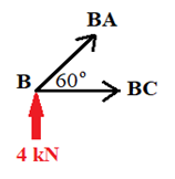
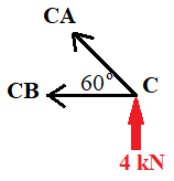
Figure 7-9(c)
As the angle between CA and CB is 60 degree, we get the same values of the forces as in the previous joint at B. Therefore we get;
CB = 2.31 kN (Tension) CA= 4.62 compressive.
In the method of virtual work we remove all the acting loads and apply 1 kN virtual load at the point of required displacement in the required direction. In this question we have to calculate the horizontal displacement at joint C. Therefore we apply 1 kN load in the horizontal direction at C and then calculate the support reactions and the member forces (n) due to virtual load.
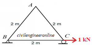
Figure 7-9(d)
Apply equilibrium equations to calculate support reactions. We find that there will be no vertical reaction. We will get only horizontal reaction which will be at support B. Hence Reaction at B is 1 kN horizontal in the opposite direction of applied force of 1 kN.
Now we consider the equilibrium of joint C to calculate the forces in the truss members CB and CA.
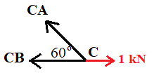
Figure 7-9(e)
Applying Σ Fx = 0;
We can easily calculate the force in CB equal to 1 kN tensile
By applying Σ Fy = 0; we get CA = 0
We do the same at joint B to get the forces in the members connected at B.

Figure 7-9(f)
We get the force in BA = 0 and BC = CB = 1 kN tensile
Now we prepare a table and enter the values of actual forces (N) and virtual forces (n) in that table as shown below.
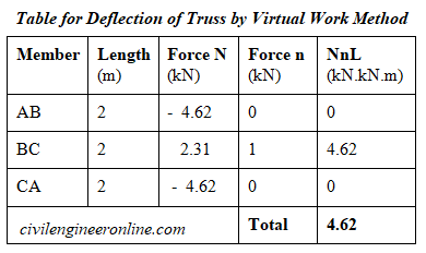
Table 7-9(a)
Now we apply the principle of virtual work
1 kN . ΔC = Σ (NnL/AE)
Area of each member = 1 cm2 = 1 x 10⁻⁴ m2
Therefore , 1 kN. ΔC =(4.62 kN. kN.m) / (10-4 m2 x 200 x 106 kN/m2)
We get on simplification
ΔC = 4.62 m / (10-4 m2 x 200 x 106) = 2.31 x 10-4 = 2.31 x 10⁻¹mm = 0.23 mm
The positive sign of displacement means that the displacement is in the direction of 1 kN virtual force in this case in the right hand direction.
You can also visit the following related links of solved examples
Excellent Calculators
Stress Transformation Calculator
Calculate Principal Stress, Maximum shear stress and the their planes
Calculator for Moving Load Analysis
To determine Absolute Max. B.M. due to moving loads.
Bending Moment Calculator
Calculate bending moment & shear force for simply supported beam
Moment of Inertia Calculator
Calculate moment of inertia of plane sections e.g. channel, angle, tee etc.
Reinforced Concrete Calculator
Calculate the strength of Reinforced concrete beam
Moment Distribution Calculator
Solving indeterminate beams
Deflection & Slope Calculator
Calculate deflection and slope of simply supported beam for many load cases
Fixed Beam Calculator
Calculation tool for beanding moment and shear force for Fixed Beam for many load cases
BM & SF Calculator for Cantilever
Calculate SF & BM for Cantilever
Deflection & Slope Calculator for Cantilever
For many load cases of Cantilever
Overhanging beam calculator
For SF & BM of many load cases of overhanging beam
More Links
Civil Engineering Quiz
Test your knowledge on different topics of Civil Engineering
Research Papers
Research Papers, Thesis and Dissertation
List of skyscrapers of the world
Containing Tall building worldwide
Forthcoming conferences
Containing List of civil engineering conferences, seminar and workshops
Profile of Civil Engineers
Get to know about distinguished Civil Engineers
Professional Societies
Worldwide Civil Engineers Professional Societies
Keep visiting for getting updated or Join our mailing list
Search our website for more...
PleaseTell your Friends about us if you find our website useful
Other Useful Links