Problem 2-1
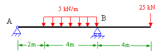
A simply supported beam is subjected to the loading as shown in figure 2-1(a). Determine the absolute maximum bending stress in the beam if the beam has a rectangular cross-section as shown in figure 2-1(b). Also draw bending stress diagram.
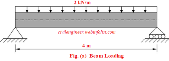
Figure 2-1(a)
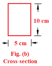
Figure 2-1(b)
The bending stress is calculated by using the bending equation given below
M / I = σ / y
Where;
M = bending moment
I = moment of inertia about neutral axis of the section
σ = bending stress
y = the distance from neutral axis to the point of bending stress
we can write;
σ = M y / I
The above relation shows that bending stress will be maximum when the distance y is maximum i.e. at the top or bottom of the section means at a distance of 5 cm from the neutral axis of this section..
Absolute maximum bending stress will occur at the section where the bending moment is maximum.
The given beam is simply supported with uniform load on the entire span. In this case the maximum bending moment will occur at the mid-span of the beam and can be calculated by the following formula
Mmax = w L2/8
Where; w = uniform load on the beam (in this problem it is 2 kN/m)
L = beam span (equal to 4 m)
Therefore Mmax = 2 x 42 / 8 = 4 kNm
You can also use our Bending Moment calculator.
For a rectangular section, Moment of inertia about the neutral axis, Ixx = bd3/12
In this section, b = 5 cm, d = 10 cm. The neutral axis is passing through the centroid of the section.
Therefore Ixx = 5 x 10³ / 12 = 0.416 x 103 cm4 = 0.416 x 10⁻⁵ m4
You can also use our moment of inertia calculator.
Absolute maximum bending stress = (Mmax) (ymax) / (Ixx);
substituting the values we get;
Absolute maximum bending stress = 4 kNm x 0.05 m / (0.416 x 10⁻⁵m4) = 0.48 x 10⁵ kN/m2 = 48 MPa
(1 MPa = 1 Mega Pascal = 106 N/m2)
You can also see our Bending Stress Calculator
The bending stress diagram will be as given below in Fig 2-1(c)
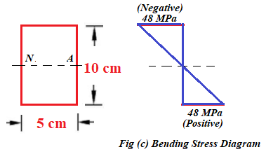
Figure 2-1(c)
The bending stress above the neutral axis (N.A.) will be compressive which is shown as negative whereas the bending stress below the neutral axis will be tensile and shown as positive.
You can visit the following links of solved examples on Bending moment and shear force calculations and plotting of diagrams
Excellent Calculators
Stress Transformation Calculator
Calculate Principal Stress, Maximum shear stress and the their planes
Calculator for Moving Load Analysis
To determine Absolute Max. B.M. due to moving loads.
Bending Moment Calculator
Calculate bending moment & shear force for simply supported beam
Moment of Inertia Calculator
Calculate moment of inertia of plane sections e.g. channel, angle, tee etc.
Reinforced Concrete Calculator
Calculate the strength of Reinforced concrete beam
Moment Distribution Calculator
Solving indeterminate beams
Deflection & Slope Calculator
Calculate deflection and slope of simply supported beam for many load cases
Fixed Beam Calculator
Calculation tool for beanding moment and shear force for Fixed Beam for many load cases
BM & SF Calculator for Cantilever
Calculate SF & BM for Cantilever
Deflection & Slope Calculator for Cantilever
For many load cases of Cantilever
Overhanging beam calculator
For SF & BM of many load cases of overhanging beam
More Links
Civil Engineering Quiz
Test your knowledge on different topics of Civil Engineering
Research Papers
Research Papers, Thesis and Dissertation
List of skyscrapers of the world
Containing Tall buildings worldwide
Forthcoming conferences
Containing List of civil engineering conferences, seminar and workshops
Profile of Civil Engineers
Get to know about distinguished Civil Engineers
Professional Societies
Worldwide Civil Engineers Professional Societies
Keep visiting for getting updated or Join our mailing list
Search our website for more...
PleaseTell your Friends about us if you find our website useful
Other Useful Links