Problem 7-1
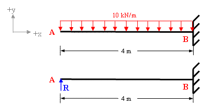
The propped cantilever with applied loading is shown in figure 7-1(a). Find the support reactions and draw Bending moment diagram.

Figure 7-1(a)
Solution:
The free body diagram of this structure in fig 7-1(b) shows that the given propped cantilever has 3 support reactions (Ay, By, MB) whereas there are only 2 equations of equilibrium (ΣFy = 0 and ΣMz = 0) available for this structure. Therefore it is statically indeterminate of degree one.

Figure 7-1(b)
To solve for the unknown reaction of this structure we need one more equation which can be obtained by compatibility. It is evident that deflection at A is zero. Considering Ay as redundant R and applying principle of superposition we get;
Total deflection at A is equal to the sum of deflection due to applied loading and deflection due to redundant R (refer to figure 7-1(c).

Figure 7-1(c)
Deflection at A due to applied loading = wL4 /8EI = (10 x 44)/8EI ↓
Deflection at A due to redundant R = (R x 43)/3EI ↑
Taking downward deflection as negative and upward as positive and applying principle of superposition.
ΣδA = (R x 43)/3EI - (10 x 44)/8EI
But ΣδA = 0 as the support A is a rigid support.
Therefore (R x 43)/3EI - (10 x 44)/8EI = 0
R = {(10 x 44)/8EI} / { ( 43)/3EI}
Hence R = 15 kN
Now we can easily determine the other reactions
By = 10 x 4 - 15 = 25 kN
MB= 15x4 - 10x4x2 = - 20 kNm (clockwise)
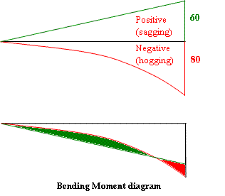
The resultant bending moment diagram shown in figure 7-1(d) is drawn by superimposing the negative moment diagram over the positive moment diagram. The positive moment diagram will be parabolic (due to udl) whereas negative moment diagram will be a straight line (due to point load)

Fig 7-1(d|)
The resultant BMD shows that this beam will have a point of contra-flexure (also known as point of inflection) which can be determined in a simple way by writing the equation of bending moment at a distance 'x' and equating it to zero because the bending moment is equal to zero at the point of contra-flexure.
Mx = 15x -10x2 /2 = 0
Therefore x = 3m from the prop A,
It is clear from the resultant BMD that the maximum bending moment value is greatly reduced.
You can also use our deflection calculator for calculating deflection to solve this problem
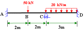
Please visit the following links of solved examples for Indeterminate Structures
You can also visit other solved examples
Excellent Calculators
Stress Transformation Calculator
Calculate Principal Stress, Maximum shear stress and the their planes
Calculator for Moving Load Analysis
To determine Absolute Max. B.M. due to moving loads.
Bending Moment Calculator
Calculate bending moment & shear force for simply supported beam
Moment of Inertia Calculator
Calculate moment of inertia of plane sections e.g. channel, angle, tee etc.
Reinforced Concrete Calculator
Calculate the strength of Reinforced concrete beam
Moment Distribution Calculator
Solving indeterminate beams
Deflection & Slope Calculator
Calculate deflection and slope of simply supported beam for many load cases
Fixed Beam Calculator
Calculation tool for beanding moment and shear force for Fixed Beam for many load cases
BM & SF Calculator for Cantilever
Calculate SF & BM for Cantilever
Deflection & Slope Calculator for Cantilever
For many load cases of Cantilever
Overhanging beam calculator
For SF & BM of many load cases of overhanging beam
More Links
Civil Engineering Quiz
Test your knowledge on different topics of Civil Engineering
Research Papers
Research Papers, Thesis and Dissertation
List of skyscrapers of the world
Containing Tall buildings worldwide
Forthcoming conferences
Containing List of civil engineering conferences, seminar and workshops
Profile of Civil Engineers
Get to know about distinguished Civil Engineers
Professional Societies
Worldwide Civil Engineers Professional Societies
Keep visiting for getting updated or Join our mailing list
Search our website for more...
PleaseTell your Friends about us if you find our website useful
 Problem
8-1New
Solution of Indeterminate beam by moment distribution method
 Problem 7-4 Solution of Indeterminate Structure by
slope-deflection equations
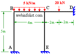
 Problem 8-2 Solution of Indeterminate Frame by using moment distribution method
 Problem 7-2 Solution of Indeterminate Structure (Continuous Beam) by consistent deformation