Absolute Maximum moment in a simple beam due to a series of 5 moving loads

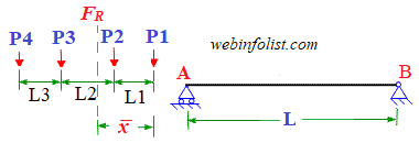
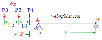
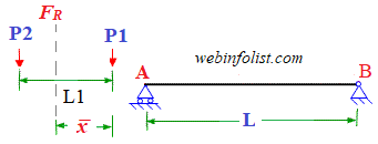
This calculator is to determine absolute maximum bending moment (BM) in a simply supported beam with span L due to 5 moving loads (P1, P2, P3, P4, P5). We know that maximum BM under a moving load occures when this load and the resultant (centroid) of the load system are placed equidistant from the beam center. Initially the calculator determines the position of resultant (FR) i.e. centroid with reference to the leading load P1. It also determines the position of centroid with reference to all the loads. If the distance of a load from the centroid is +ve, it is on the right of the centroid whereas if this distance is negative that load is on the left of the resultant. The concept of influence line diagram (ILD) is used to determine values of BM. This calculator uses trial and error method to determine the maximum BM under each load and finally the maximum of all the trials is taken as the absolute maximum bending moment. It also tells under which load the absolute maximum BM occures and what is its location from support A. Please note that this calcultor works when the distance between the first and last load is not more than the mid-span.
By default this calculator is using the units of load as 'kN', distance as 'm' and BM as 'kNm'. Other units like kip for load, ft for distance and ft-kip for BM can also be used to get the result in the relevant units without affecting the calculated values.
Please refer to the figure and enter the required values in the form given below and then click "Calculate".
You are also welcome to send your Feedback
Other Calculators for Analysis of Moving Loads
Please Tell your Friends about us
Keep visiting for getting updated or Join our mailing list to get updates
Favourite Links
Stress Transformation Calculator
Calculate Principal Stress, Maximum shear stress and the their planes
Calculator for Moving Load Analysis
To determine Absolute Max. B.M. due to moving loads.
Bending Moment Calculator
Calculate bending moment & shear force for simply supported beam
Moment of Inertia Calculator
Calculate moment of inertia of plane sections e.g. channel, angle, tee etc.
Shear Stress Calculator
Calculate Transverse Shear Stress for beam sections e.g. channel, angle, tee etc.
Reinforced Concrete Calculator
Calculate the Strength of Reinforced Concrete beam
Deflection & Slope Calculator
Calculate deflection and slope of simply supported beam for many load cases
Fixed Beam Calculator
Calculation tool for bending moment and shear force for Fixed Beam for many load cases
BM & SF Calculator for Cantilever
Calculate SF & BM for Cantilever
Deflection & Slope Calculator for Cantilever
For many load cases of Cantilever
Overhanging beam calculator
For SF & BM of many load cases of overhanging beam
More Links
Civil Engineering Quiz
Test your knowledge on different topics of Civil Engineering
Statically Indeterminate Structures
Definition and methods of solving
Solved Examples
Truss Member Forces calculation
using method of joints and method of sections
Shear force and bending moment
Illustrated solved examples to draw shear force and bending moment diagrams
Slope and deflection of beam and Truss
Illustrated solved examples to determine slope and deflection of beam and truss
Solution of indeterminate structures
slope deflection, moment distribution etc.
Reinforced concrete beam
Solved examples to determine the strength and other parameters
Calculation of bending stress in a beam
using bending equation and plotting the bending stress diagram
Other Useful Links
Skyscrapers of the world
Containing Tall building worldwide
Profile of Civil Engineers
Get to know about distinguished Civil Engineers
Professional Societies
Worldwide Civil Engineers Professional Societies
Please Tell your Friends about us
Search our website for more...


